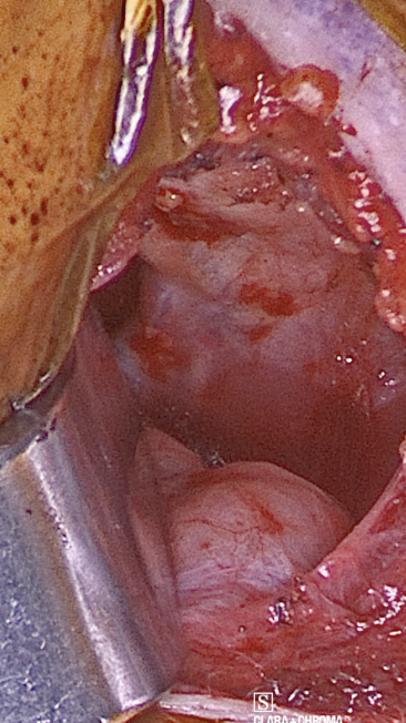
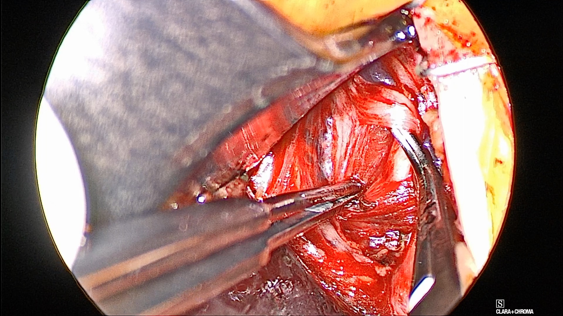
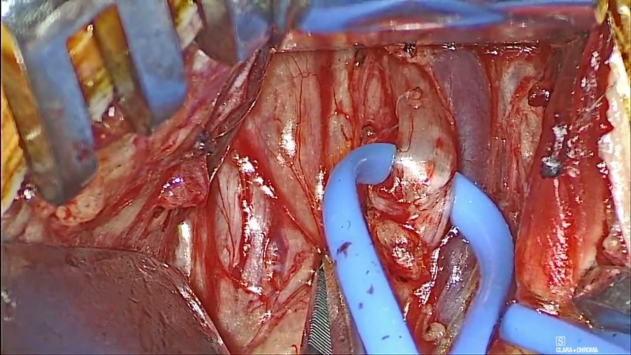
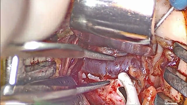
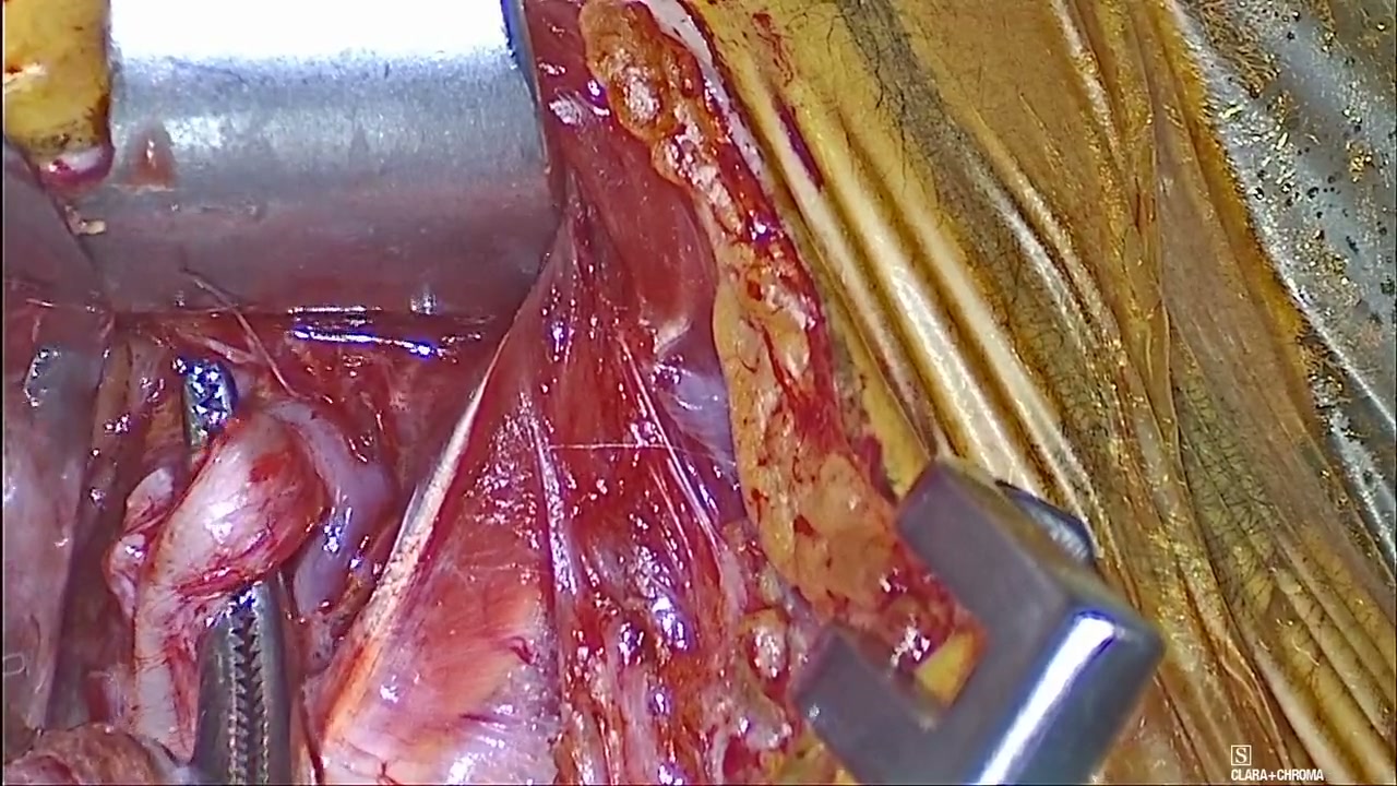
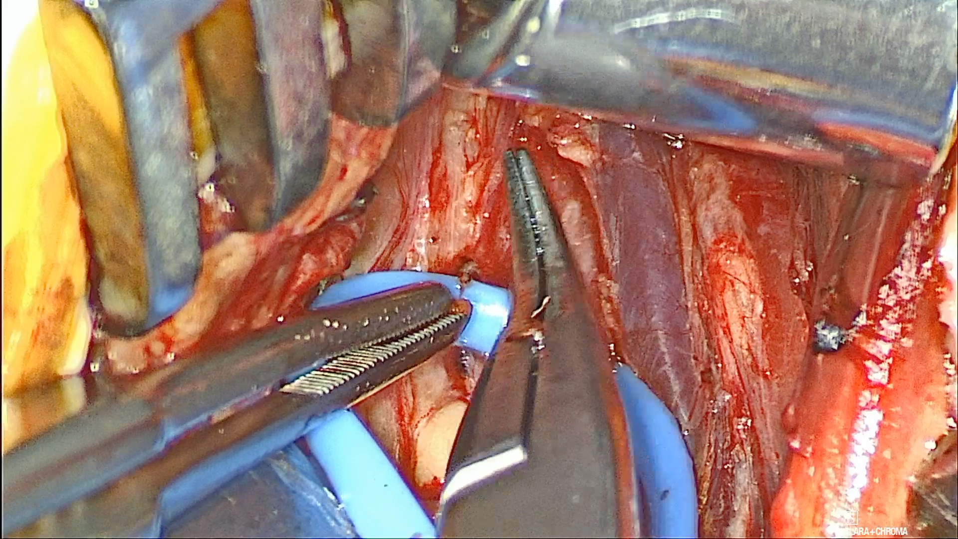
Learn the key steps of the Inspire procedure, taught with the current Inspire V system. Each step includes key learning points, from the basics to more advanced considerations. Operative videos from my teaching collection illustrate the technique, and questions help you test your understanding.
Inspire procedure overview: nerve exposure and cuff placement. Procedure context
Before you enter the room
Review the sleep study. Review the diagnostic study date, AHI, central and mixed events, oxygenation, and positional pattern. Note whether the study used a 3% or 4% hypopnea definition.
Review prior treatments. Inspire is a second-line treatment. Know what the patient has previously tried: CPAP, BiPAP, an oral appliance, or prior surgeries, including nasal surgery. Review the response to each treatment, any residual OSA, and barriers to effective use.
Review the DISE. Describe the velum, oropharyngeal lateral walls, tongue base, and epiglottis. At each site consider degree and configuration. Complete concentric collapse at the soft palate excludes Inspire under the label; lateral-wall collapse is a separate finding to discuss.
Understand FDA and payer criteria. Compare FDA labeling with the patient’s individual payer criteria; they can differ substantially. For most adults, FDA labeling includes AHI 15–100, age 22 or older, PAP failure or intolerance, and absence of palatal complete concentric collapse. Central plus mixed events above 25% are a contraindication. Younger patients have additional criteria.
Before moving on: Explain why Inspire is appropriate for this patient using the sleep study, prior treatment history, DISE findings, and the patient’s payer criteria.
Example payer criteria: Medicare LCD L38276. An illustrative Medicare local coverage policy. Review the policy applicable to the individual patient; these criteria do not represent every payer.
Lesson 02About 8 minInspire
Prep and room setup
Review the instruments and preoperative medications, position the patient for exposure, establish NIM monitoring, and complete the sterile prep.
Instruments for the case
Review the instrument set with the scrub team before the case. The full set contains 35 instruments across 21 types. These are the key tools to have ready for each part of the procedure.
Exposure. Use a curved tonsil clamp for the initial neck dissection and a Kelly clamp with a peanut for blunt dissection. Have skin rakes and plastic Army–Navy (TESSA) retractors available, with a Langenbeck for deeper pocket exposure, especially in patients with obesity. A blunt Weitlaner assists chest dissection down to the pectoralis fascia.
Nerve and breakpoint dissection. Use a McCabe nerve dissector to separate nerve fibers and remove fascia, smooth Gerald forceps to grasp fine fascia, and a baby right-angle clamp for breakpoint dissection.
Hemostasis and suction. Have titanium bipolar forceps and a pediatric Yankauer suction with a detachable tip ready.
Cuff placement. Use the Gemini right-angle clamp in the right hand and the Research Crile in the left hand to grasp and guide the cuff.
Suturing and closure. Have Webster and Crile-Wood needle holders, Adson forceps with teeth, and straight Mayo scissors available.
Plan preoperative medications. Communicate early with anesthesia to plan short-acting neuromuscular blockade and confirm recovery before nerve mapping. If nasotracheal intubation is planned, use oxymetazoline (Afrin) in pre-op as agreed with anesthesia. Ensure appropriate antibiotics are given before incision, such as weight-based cefazolin (Ancef), with selection guided by the patient’s allergy history, MRSA colonization status, and local prophylaxis protocol.
Position the patient. Agree with anesthesia on 90° versus 180° table rotation. Use a shoulder roll to allow adequate neck extension, and keep the head well supported on a donut. Turn the head away from the operative side and position the patient closer to the side where the surgeon will stand. Tuck the right arm for a right-sided implant, or both arms if planning to begin the chest and neck incisions simultaneously.
Keep the tongue visible. Plan a clear view of tongue protrusion before draping. Discuss nasotracheal intubation with anesthesia; keeping the tube out of the oral cavity makes tongue movement easier to assess.
NIM setup. Set up the NIM Vital and place the recording electrodes before nerve mapping.
Red channel: styloglossus (exclusion). Place the recording electrode 3 cm from the tip of the tongue, just inferior to the papillated portion on the smooth mucosa. It should be superficial enough to see the outline of the metal beneath the tissue, without the metal surface being exposed.
Blue channel: genioglossus (inclusion). Place the recording electrode anterior to the papilla, off midline, at a 45° angle. Take care not to skive along the mandible.
Confirm each recording electrode’s position, channel assignment, and secure seating. Check the ground and reference connections.
Incision guidance. Palpate the anterior edge of the submandibular gland (SMG) before marking the incision. Plan a 3 cm incision one fingerbreadth below the mandible, parallel to relaxed skin tension lines, overlapping the anterior edge of the submandibular gland by 5 mm and extending anteriorly. Specifics may vary with attending preference; confirm the planned landmarks and exposure with your attending.
Incision planning and orientation 0:32 · Shared technique · Silent · Written viewing guide
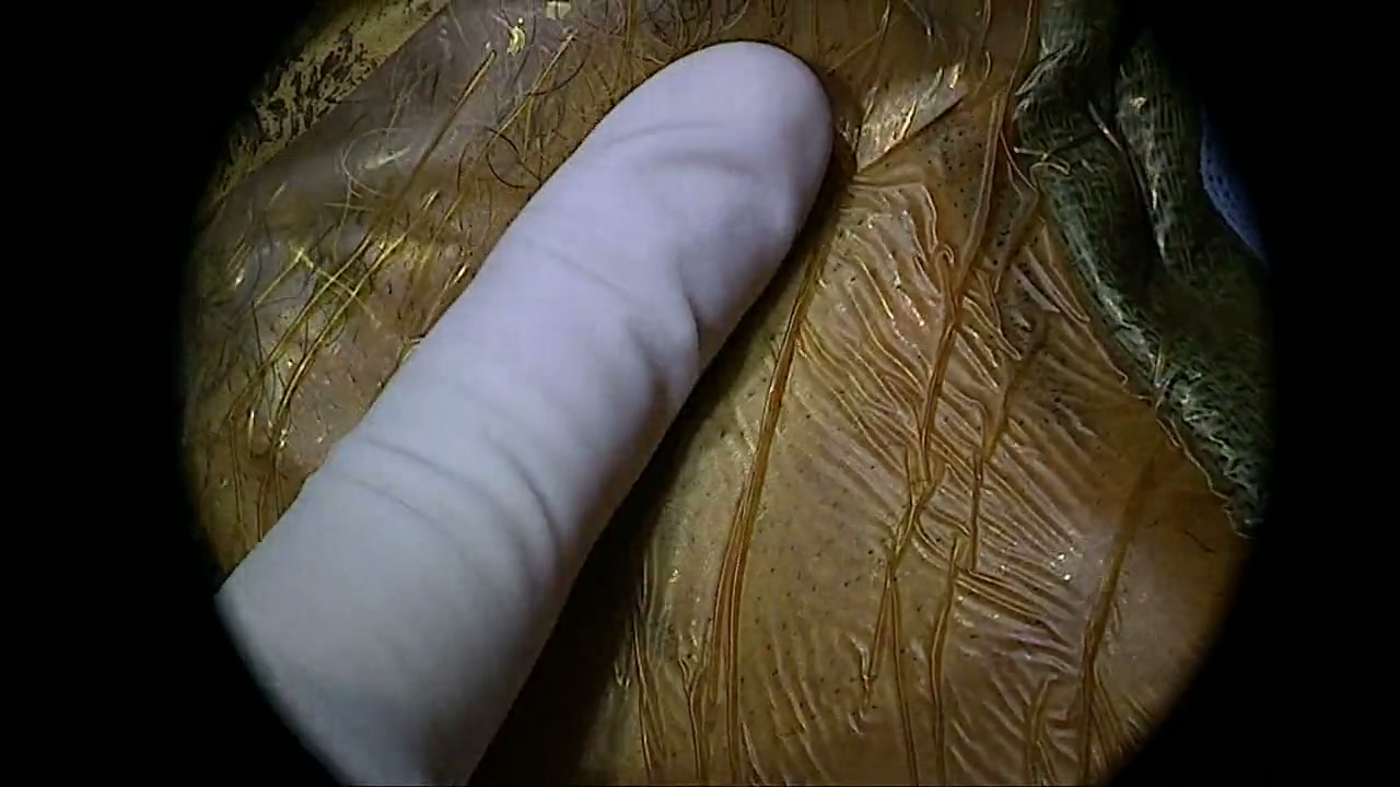
Incision guidance: Practice palpating the submandibular gland (SMG) with one finger. Use light pressure and feel the anterior edge roll beneath your finger. With experience and continued practice, this landmark becomes easier to identify, even in patients with obesity. The anterior gland edge is the key anchor for accurate incision placement. Locate it first, then use the incision measurements in this lesson to place the mark.
Written video guide
Watch the one-finger palpation of the SMG. Feel for the anterior edge rolling beneath your finger with light pressure, then relate that landmark to the incision and planned mylohyoid exposure.
Incision guidance: 3 cm, one fingerbreadth below the mandible, parallel to relaxed skin tension lines. Overlap the anterior edge of the submandibular gland by 5 mm, then extend anteriorly. Specifics may vary with attending preference.
Source: Ryan Nord, MD. Shared neck technique; recorded implant model not identified
Surgical prep. When using combined Betadine/chlorhexidine prep, apply Betadine scrub and blot the excess, then apply Betadine paint and blot, followed by chlorhexidine. Wait at least 3 minutes before draping and confirm the prep is completely dry, following the product’s instructions. Keep chlorhexidine out of the eyes, ears, and mouth. Once the prep is dry, cover the oral cavity with a clear or semi-clear sterile drape, such as a 10-10 or 10-12 drape, so tongue protrusion remains visible.
“Your gland should be at the most posterior aspect of your incision.”
Provide adequate neck extension, support the head, turn it away from the operative side, and position the patient closer to the surgeon.
Set up to see tongue protrusion clearly. Consider nasotracheal intubation with anesthesia and use a clear or semi-clear sterile drape over the mouth.
Confirm recovery from neuromuscular blockade and check the recording electrodes before nerve mapping. Give the planned antibiotics before incision.
Use the palpated anterior edge of the SMG to anchor the incision. Overlap the gland by 5 mm, then extend anteriorly.
Pitfalls
Obscuring tongue protrusion with the tube or drapes.
Focusing on NIM signals too early instead of using the anatomy to identify the breakpoint.
Marking the incision without identifying the anterior gland border and relaxed skin tension lines.
Inadequate neck extension or poor patient positioning that limits exposure.
Before moving on: Confirm the head is supported, the operative sites are accessible, the tongue is visible, and monitoring works. Confirm pre-incision antibiotics and complete drying of the surgical prep.
After making the incision and dividing the platysma, identify the submandibular gland (SMG). Use the gland and digastric to establish orientation, then define the free edge of the mylohyoid before searching deeper for the hypoglossal nerve.
Find the submandibular gland (SMG) 2:04 · Shared technique · Silent · Written viewing guide
Watch for: Start with the earlier neck exposure and identify the submandibular gland (SMG). Keep the gland as your landmark as the dissection proceeds toward the digastric and mylohyoid. Then watch the next clip for a closer view of the mylohyoid free edge.
Written video guide
Identify the submandibular gland as the superficial exposure develops.
Watch how the fascial release and retraction open the working space around the gland.
Use the gland, digastric, and mylohyoid to orient the deeper exposure before searching for the nerve.
Continue with “Define the free edge of the mylohyoid” for a closer view of that landmark.
Source: Ryan Nord, MD. Initial neck exposure continuing into deeper dissection. The recorded implant model is not identified.
Define the free edge of the mylohyoid 1:23 · Shared technique · Silent · Written viewing guide
Watch for: Follow the blunt dissection to the free edge of the mylohyoid. Re-establish that landmark before deciding which nerve is in view.
Written video guide
0:00–0:16: Define the free edge of the mylohyoid before identifying the nerve.
0:26–0:42: Follow the blunt dissection as the gland–mylohyoid plane opens.
1:02–1:20: Reorient to the exposed landmarks and identify the hypoglossal nerve by its anatomy.
Source: Ryan Nord, MD. Shared neck technique; recorded implant model not identified
Work through the steps
Open one layer at a time. Proceed through skin, subcutaneous tissue, and platysma with careful hemostasis. Protect the facial nerve branches that contribute to lower-lip movement.
Find the gland’s anterior border. Palpate and identify the submandibular gland. Define its anterior border and keep the dissection in front of the gland.
Separate the gland from the mylohyoid. Open the fascial interface between the gland and mylohyoid. Mobilize the anterior gland so it can move posteriorly and superiorly without excessive force.
Identify the digastric. Knowing the anatomy lets you move quickly and safely. Follow the anterior belly of the digastric to its intermediate tendon. With the tendon and anterior border of the submandibular gland clearly exposed, divide the overlying connective tissue in the plane immediately superficial to the tendon and anterior to the gland to complete the exposure. This is why the digastric is the “resident’s friend”: it gives you a clear landmark for efficient dissection.
Define the free edge of the mylohyoid. Use blunt dissection at the gland–mylohyoid interface. Define the posterior free edge and retract the muscle anterosuperiorly to see the deeper plane.
Check exposure before advancing. When the nerve is difficult to find, return to the gland, fascia, digastric, and mylohyoid. Restore a clear working window before dissecting deeper.
Dr. Nord’s teaching
“Make sure you're getting in front of the submandibular gland, not under it. So make sure you're consciously separating the submandibular gland from the mylohyoid and seeing that separation.”
Find the submandibular gland and its anterior border first. Use the digastric and mylohyoid to stay oriented.
The digastric is the “resident’s friend.” Identify its tendon and the anterior gland border, then use the plane immediately superficial to the tendon and anterior to the gland to divide connective tissue and open the exposure efficiently.
Release the fascia between the gland and mylohyoid so the gland can be retracted without excessive force.
Define the posterior free edge of the mylohyoid before looking deeper for the hypoglossal nerve. If exposure is poor, return to these landmarks.
Pitfalls
Working under the submandibular gland instead of in front of it, which limits exposure.
Pulling harder on the gland before separating it from the mylohyoid.
Losing the exposure plane immediately superficial to the digastric tendon and anterior to the gland.
Searching for the hypoglossal nerve before defining the posterior free edge of the mylohyoid.
Before moving on: Point to the digastric, gland, and mylohyoid free edge before naming the nerve.
The first cervical branch of the facial nerve runs over and in front of the submandibular gland, within the deep cervical fascia, on its course toward the lower lip, and it can be exposed immediately after the platysma is incised. Recognize its anatomy and appearance so you do not injure it and leave your patient with postoperative lower-lip weakness.
Work through the steps
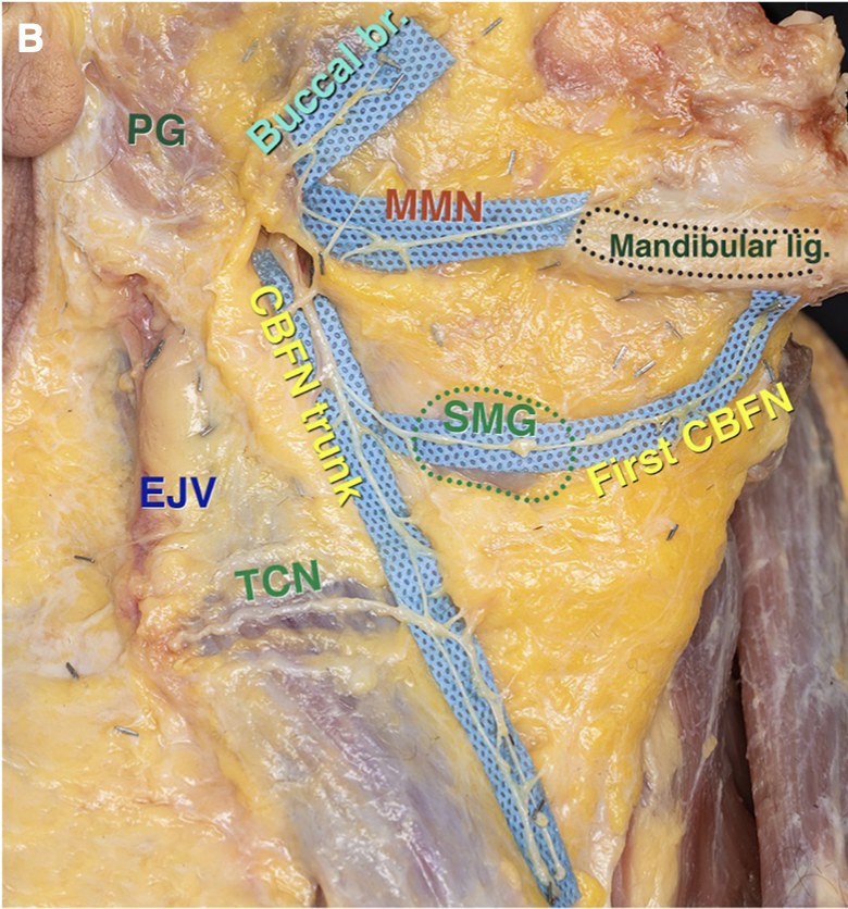
Know where the branches run. The first cervical branch of the facial nerve (CBFN) leaves the cervical trunk soon after the trunk exits the parotid gland. It runs deep within the investing layer of the deep cervical fascia, then becomes more superficial at the submandibular gland, where its terminal branches run just outside the gland capsule and, anterior to the gland, immediately deep to the platysma. It ends at the mandibular ligament, where the platysma, depressor labii inferioris and depressor anguli oris attach to the mandible. Because the platysma and depressor labii inferioris function as one muscle unit, injury to this branch causes lower-lip depressor dysfunction.
The marginal mandibular nerve is not the nerve at risk here. It crosses the mandibular border superficial to the facial vessels and runs along the mandible, well above an incision placed one fingerbreadth below it.
The first cervical branch crosses the submandibular gland
Cadaver dissection with the platysma removed and the nerves exposed within the deep fascia. The first cervical branch of the facial nerve (First CBFN) leaves the cervical trunk near the parotid gland, crosses over the submandibular gland (SMG) just outside its capsule, and ends below the mandibular ligament, where the platysma and lower-lip depressors attach. The marginal mandibular nerve (MMN) crosses the mandible and passes within 2 mm of the mandibular ligament.
Source: Minelli et al., The Functional Anatomy and Innervation of the Platysma is Segmental (2023), Figure 5B, shown without panels A, C and D. Open-access article. License: CC BY-NC 4.0. View full-size image
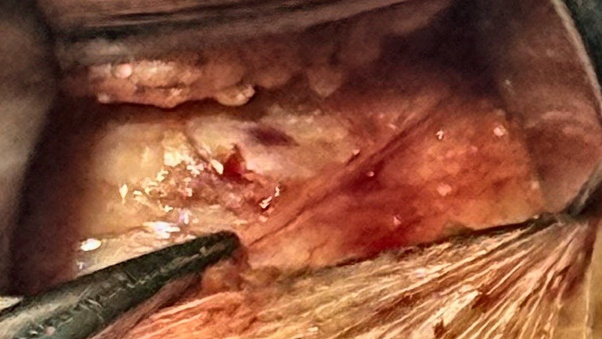
Keep the incision anterior. The 3 cm incision one fingerbreadth below the mandible, starting at the anterior edge of the gland and extending forward, limits the dissection to the front of the gland and keeps most cervical branches out of the field. It reduces the risk without eliminating it: the case photograph in this lesson shows a cervical branch in the exposure.
Consider blunt dissection of the platysma. In most head and neck operations the platysma is divided without a second thought, but consider where this incision sits. Incisions near the facial nerve branches are usually kept at least two fingerbreadths below the mandible; this one is typically one fingerbreadth below it and more anterior than in most head and neck cases, so this layer calls for more care. The platysma also inserts into the lower lip, so dividing it alone can cause temporary lower-lip weakness.
Instead of cutting it sharply, use a tonsil clamp to create a vertical pocket in the platysma, then stretch it out of the field with two plastic Army–Navy (TESSA) retractors. This keeps electrocautery, and the current it can transmit, away from the nerve, preserves the fascial planes, and makes an aberrant cervical branch likely to be identified before it is injured. At the end of the case, the intact platysma closes quickly with one or two sutures.
Test any suspected nerve with the NIM probe. Use the NIM probe to test any suspected nerve fiber over the gland and watch for movement in the lower lip. If the lip moves, preserve the branch and work around it.
Lower-lip movement can also follow stimulation of the sensory transverse cervical nerve, whose branches communicate and run with the cervical branch. Either way, preserve any fiber that moves the lip.
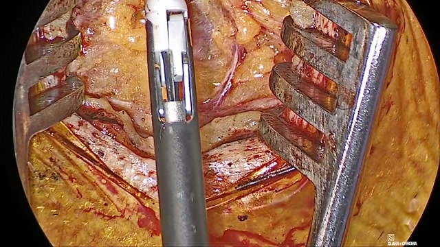
A cervical branch in the exposure
The instrument points to a cervical branch of the facial nerve over the submandibular gland, exposed immediately after the platysma was opened in an Inspire case. Cropped to the open wound, with contrast adjusted.
Stimulate before using energy over the gland. Bipolar cautery or a sealing device on the anterior gland can injure a cervical branch running just outside the capsule. Before using energy there, stimulate the tissue with the NIM probe and watch the lower lip. If it moves, move away from that tissue.
Recognize lower-lip depressor dysfunction. Injury to the first cervical branch denervates the depressor labii inferioris and platysma while the mentalis keeps working, so lower-lip depression is lost on that side, most evident on smiling, and lip eversion is preserved. Neuropraxia from traction typically recovers within about three months; a transected branch may not.
Lower-lip weakness is likely underreported. Over one year it accounted for 9 of 132 adverse events (6.8%) described by patients in hypoglossal nerve stimulation Facebook groups, but 2 of 428 MAUDE reports (0.4%), and one of those two required reoperation to repair a facial nerve transected during implantation.
“Don't cut through the platysma. We're gonna spread it. Just get down to the platysma.”
The nerve at risk in this exposure is the first cervical branch, not the marginal mandibular nerve, which runs along the mandible well above the incision.
Open the platysma bluntly: create a vertical pocket with a tonsil clamp, then stretch it out of the field with two TESSA retractors.
Test any suspected nerve fiber with the NIM probe and watch the lower lip.
Stimulate before using energy over the gland.
Pitfalls
Dividing the platysma sharply or with cautery over the gland, where the first cervical branch can lie immediately beneath it.
Watching for the marginal mandibular nerve while overlooking the first cervical branch, the nerve actually at risk in this exposure.
Dividing a suspected nerve fiber over the gland, or using energy near it, before testing it with the NIM probe.
Before moving on: Before dissecting over the gland, point to where the first cervical branch could cross it and describe how you would test a suspected nerve fiber.
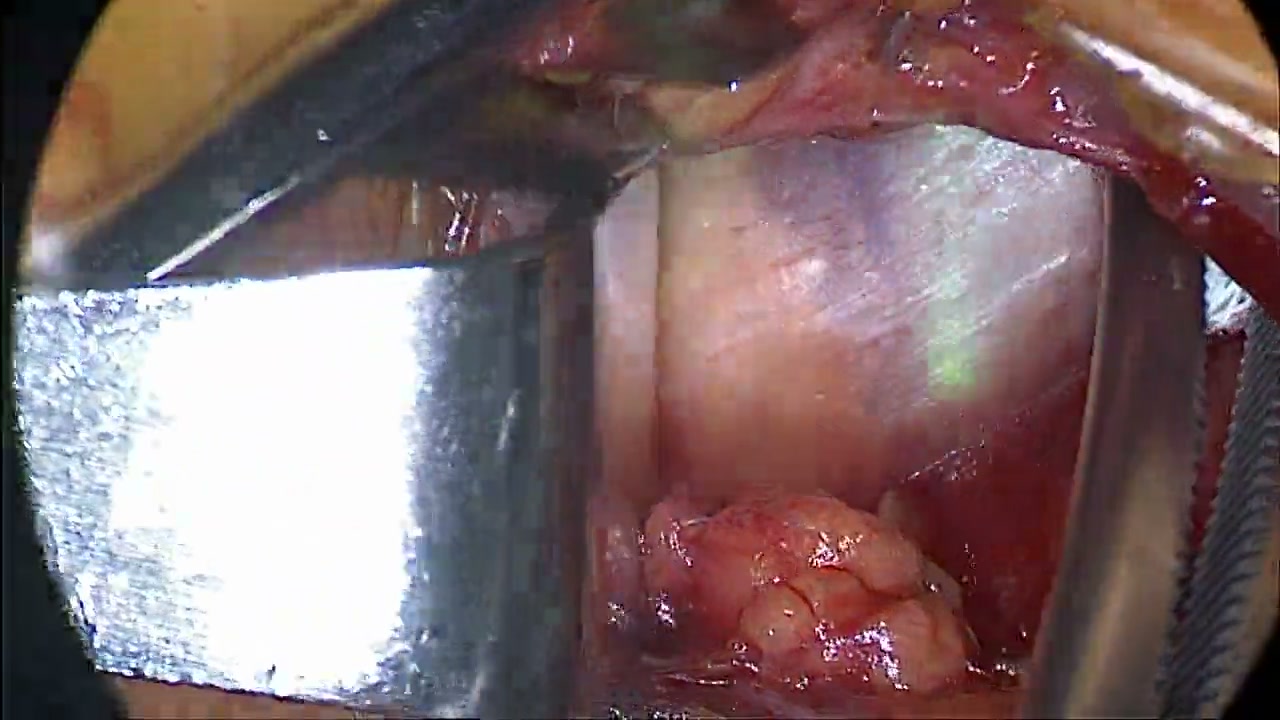
Watch for: This teaching case shows the nerve to mylohyoid producing an apparent inclusion response on NIM, followed by correct identification of the hypoglossal nerve. Recognize the mylohyoid free edge and the hyoglossus to orient the dissection and identify the correct nerve.
Written video guide
0:00–0:10: The nerve to mylohyoid produces an apparent inclusion response on NIM.
0:14–0:28: Follow the dissection between the submandibular gland and mylohyoid.
0:46–1:01: Identify the hypoglossal nerve in the deeper plane.
Source: Ryan Nord, MD. Shared neck technique; recorded implant model not identified
Recognize the lingual nerve 0:24 · Shared technique · Silent · Written viewing guide
Watch for: The lingual nerve lies superior to the hypoglossal nerve, but at times can lie lower than expected and cause confusion. Use its anatomic course to distinguish it from the hypoglossal nerve.
Written video guide
The lingual nerve normally lies superior to the hypoglossal nerve; the source slide highlights that it may be ptotic and appear lower than expected.
Use the nerve’s location, course, and expected response to distinguish it from the hypoglossal nerve.
Source: Ryan Nord, MD. Shared neck technique; recorded implant model not identified
Work through the steps
Identify the nerve over the hyoglossus. Look deep to the retracted mylohyoid edge for the hypoglossal nerve crossing the hyoglossus.
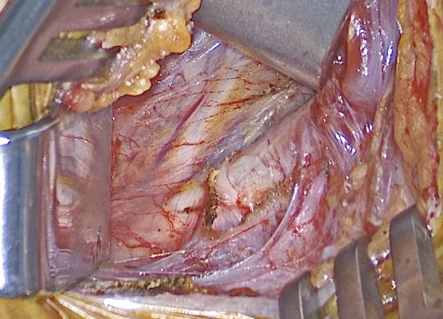
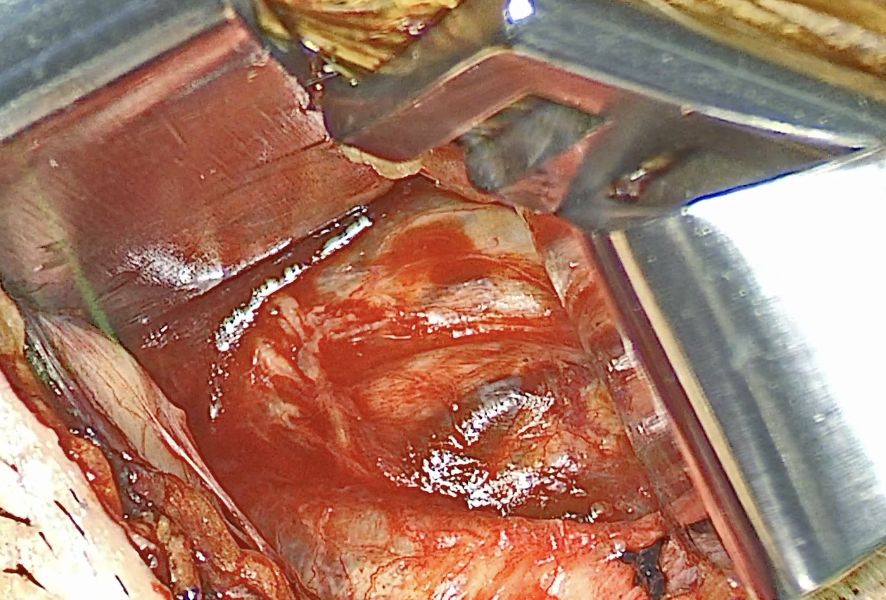
The fascia over the nerve varies considerably. It may be thin and transparent, allowing full visualization of the nerve and its branches, or so thick that the nerve cannot be seen at all.
When thick fascia obscures the nerve, identify the ranine vein and use it to locate the hypoglossal nerve superior to it. Keep the mylohyoid free edge and hyoglossus in view to stay oriented.
These three operative examples progress from thin, transparent fascia to fascia thick enough to conceal the nerve. When the nerve is hidden, use the ranine vein to locate the nerve above (superior to) the vein.
Source: Ryan Nord, MD.
Distinguish nearby nerves. The nerve to mylohyoid is a mandibular-division trigeminal branch supplying mylohyoid and anterior digastric. It can branch, accompany a vessel, and create a confusing recorded response. The lingual nerve lies superior to the hypoglossal nerve, but at times can lie lower than expected and cause confusion.
Confirm structure and response together. State where the structure came from, where it is going, and what moves when stimulated. If these disagree, stop and re-establish the plane.
Open the covering fascia carefully. Remove enough fascia to see the trunk and branching pattern. Handle the nerve gently and preserve its small nutrient vessels rather than stripping it bare.
Divide crossing veins. Divide veins that cross over the nerve to obtain full visualization of the hypoglossal nerve and its branches. Identify and isolate the vein from the nerve, then seal and divide it. Consider a vessel-sealing instrument for hemostasis and efficiency.
Some vessel sealers can produce an unintended stimulation response during activation. Keep the instrument tips in view and avoid passing beyond the intended vessel or contacting the nerve. If unexpected stimulation occurs, stop activation and reassess before continuing; direct contact and thermal spread can injure the nerve.
Crossing branch of the ranine vein
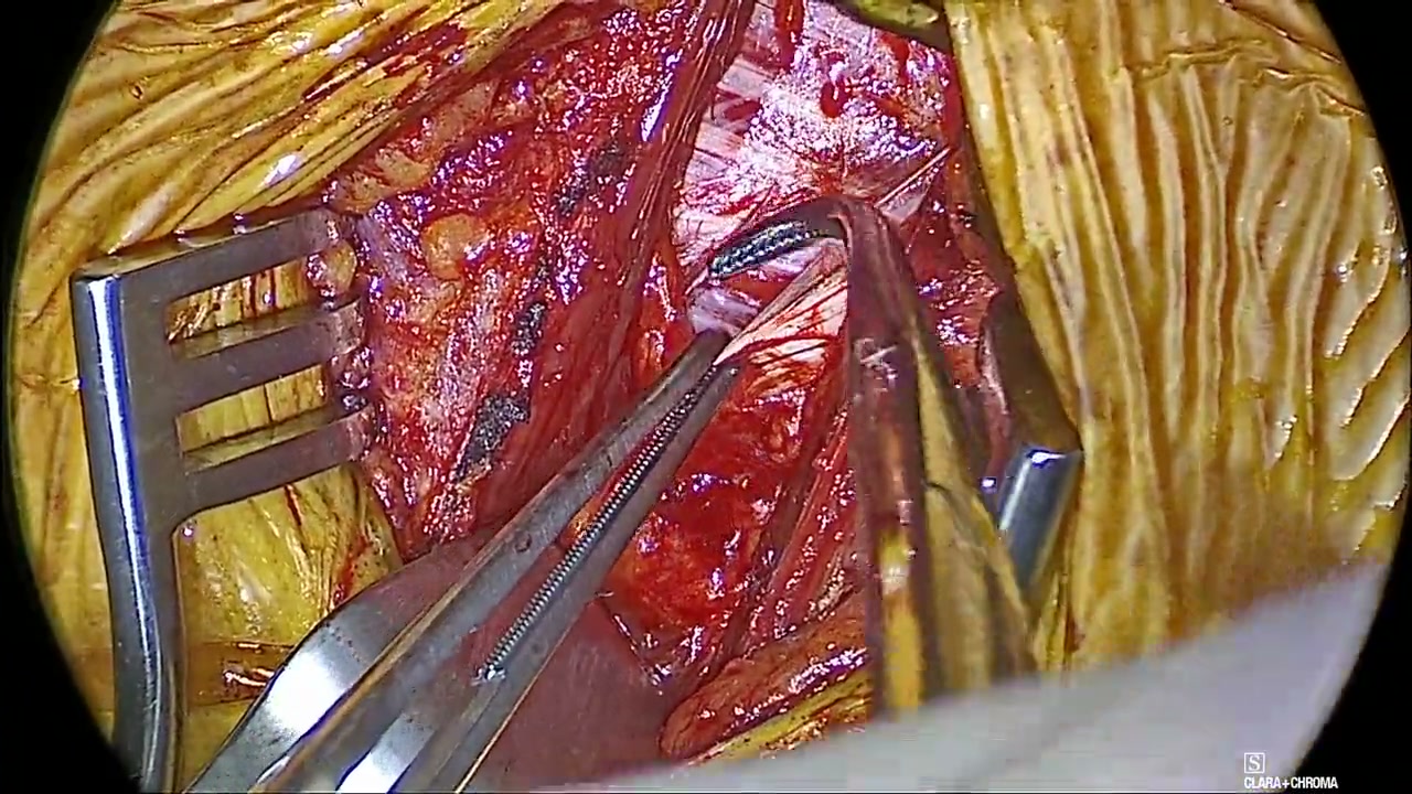
The arrow marks a small crossing branch of the ranine vein. Divide it to fully visualize the nerve and its branches. In this example, the crossing lies near the final true breakpoint and helps define how far distally the dissection needs to extend.
Watch for: Watch how the crossing vein is isolated, sealed, and divided to improve the view of the nerve and its branches. Follow the instrument tips and their relationship to the nerve throughout the maneuver.
Written video guide
Identify the crossing vein and its relationship to the underlying nerve.
Watch the vein being isolated, sealed, and divided with the instrument tips in view.
Inspect the improved exposure and hemostasis after division. The teaching goal is a clear view of the nerve and its branches.
Source: Ryan Nord, MD. Crossing-vein control during neck exposure. The recorded implant model is not identified.
Dr. Nord’s teaching
“Normally when the vein crosses over like that, the rule is just divide it because it's not helping you see what you need to see.”
Identify the hypoglossal nerve by its course over the hyoglossus, deep to the mylohyoid. A stimulation response alone does not establish nerve identity.
Fascia can be transparent or thick enough to hide the nerve completely. When the nerve is obscured, use the ranine vein as a landmark and look for the nerve superior to the vein.
The nerve to mylohyoid can produce a misleading NIM response. The lingual nerve is superior to the hypoglossal nerve but can lie lower than expected.
Isolate and divide small crossing veins for full visualization. The ranine-vein crossing shown here also helps orient the distal dissection near the final breakpoint.
Pitfalls
Looking for the hypoglossal nerve before positively identifying key landmarks, especially the free edge of the mylohyoid.
Losing orientation when thick fascia obscures the nerve and overlooking the vessel anatomy that helps identify it.
Leaving crossing veins in place when they obscure the nerve and its branches.
Aggressively stripping fascia from the nerve and risking neurapraxia.
Before moving on: Show the nerve’s course deep to the mylohyoid and over the hyoglossus, then explain the tongue response to stimulation.
CoolSeal Reveal instructions for use. Rev 002, August 2025, pp. 4–5: precautions for thermal effects near nerves, nerve monitoring, and conductive fluids. Follow the instructions for the instrument used.
CoolSeal generator user guide. Rev 007, November 2024, printed p. 18: abnormal neuromuscular stimulation requires stopping and evaluating the response.
Lesson 06About 10 minInspire
Separate inclusion and exclusion
Find the initial breakpoint, then inspect distally for a small late retractor branch near the anterior edge of the hyoglossus.
Breakpoint: estimate, then verify 0:35 · Shared technique · Silent · Written viewing guide
Watch for: Use the longitudinal vessel to estimate the initial breakpoint. Preserve it during branch separation, then inspect distally for a late retractor. A reassuring NIM response does not establish that the dissection is complete.
Written video guide
0:00–0:08: Use the longitudinal vessel to estimate the initial breakpoint.
0:09–0:21: NIM appears reassuring. Continue inspecting the branches before accepting the breakpoint.
0:24–0:35: Compare the deeper exposure with your initial branch map.
Source: Ryan Nord, MD. Shared neck technique; recorded implant model not identified
Work through the steps
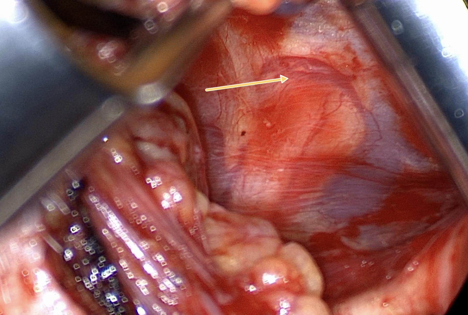
Predict the breakpoint. Use the branching pattern and the longitudinal nutrient vessel to locate the plane between inclusion and exclusion fibers. Preserve the vessel as you separate the branches, and confirm the map with stimulation and tongue movement.
Vasa nervorum: a landmark for branch separation
The arrow marks a longitudinal vessel of the vasa nervorum traveling with the hypoglossal nerve. In this view, it marks the inclusion–exclusion plane: the fibers superior to the vessel are all exclusion fibers.
Map the desired function. The intended response combines genioglossus protrusion and transverse/vertical tongue stiffening without opposing retraction. Identify the C1/geniohyoid contribution and discuss its handling with the attending.
Separate opposing branches. Define the branches producing retraction, including hyoglossus-related activation, and keep them outside the planned inclusion group. Open a visible plane with gentle spreading.
Look for the Wishbone Sign. After gently spreading at the initial breakpoint between inclusion and exclusion fibers, look distal to the spreading instrument. If the nerve bundles come back together, they form a wishbone appearance. This sign indicates a small retained retractor branch that needs to be fully dissected out of the inclusion group.
Wishbone Sign
Look for the nerve bundles coming back together distal to the spreading instrument. This appearance indicates a retained retractor branch that still needs to be separated from the inclusion group.
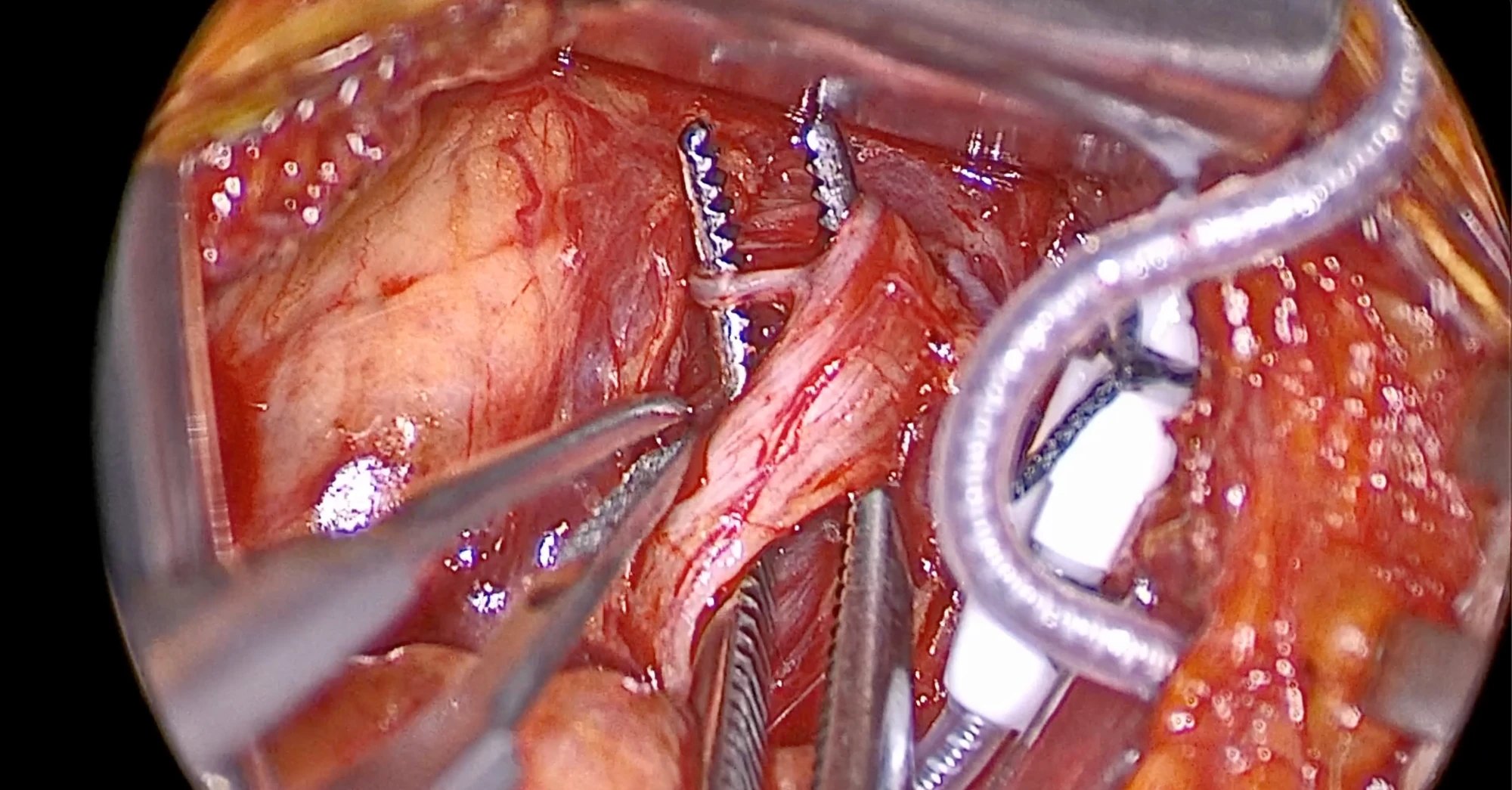
Hunt for a late retractor branch. Even when you feel you have quickly found the final breakpoint, keep looking. A small late retractor branch may still be traveling with the inclusion fibers.
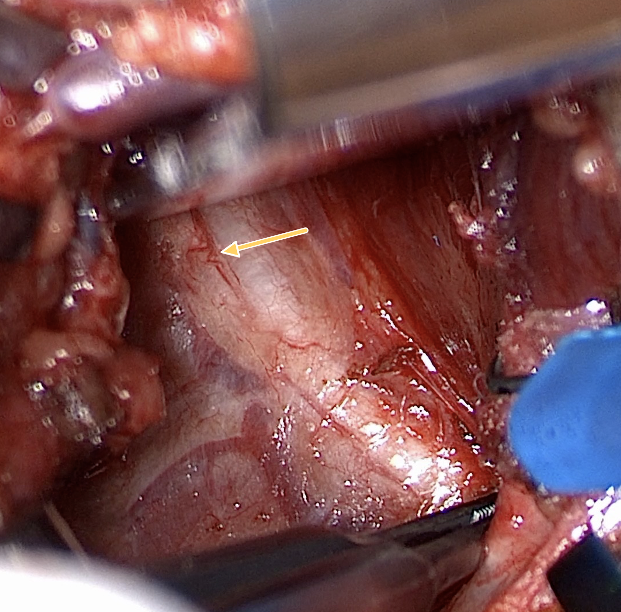
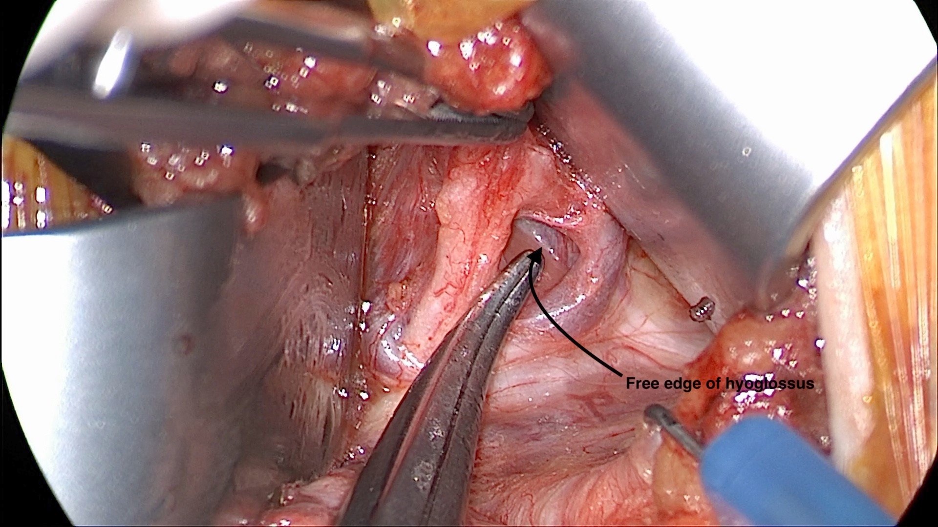
Inspect near and just beyond the anterior edge of the hyoglossus. A small retractor branch may turn back toward the muscle here and be easy to miss. Use the muscle edge to orient the distal dissection, trace the branch’s course, and fully separate it from the inclusion fibers before choosing the cuff segment.
The free edge of the hyoglossus
The arrow and the forceps tip mark the free (anterior) edge of the hyoglossus. This edge orients the distal dissection: a small late retractor branch may turn back toward the muscle at or just beyond it.
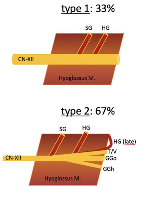
Late retractor branches: about two-thirds in Heiser’s series
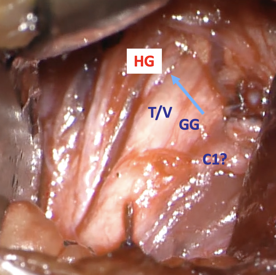
Heiser and colleagues found type 2 final hyoglossus branching in 67% of their 30-patient series. The late exclusion branch can be small and difficult to see. In the operative photograph, the blue arrow points to the late HG branch beside the inclusion fibers. Trace it back toward the hyoglossus and separate it before choosing the cuff segment.
HG: hyoglossus; SG: styloglossus; T/V: transverse and vertical tongue muscles; GGo/GGh: oblique and horizontal genioglossus compartments. The photograph’s “C1?” label preserves the uncertainty in the source image.
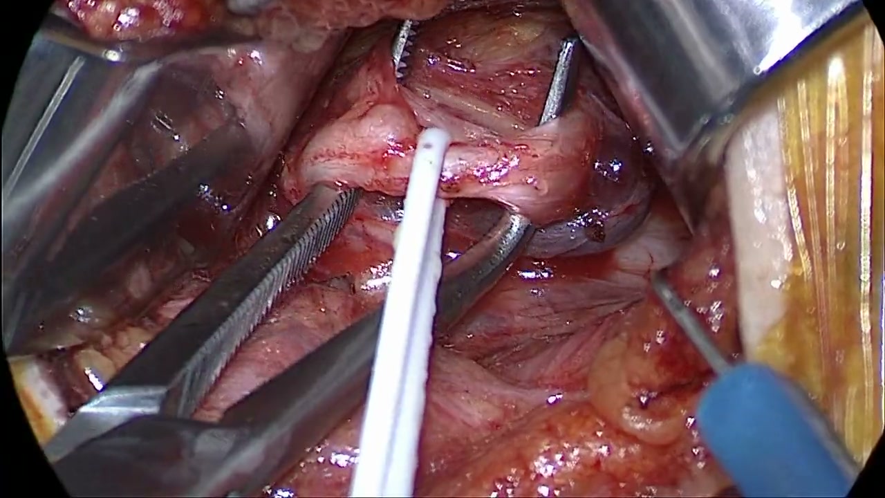
A thin branch leaves the upper part of the main nerve bundle and hooks around the left of two toothed metal tines at the top center of the field. Identified at surgery as a late retractor branch still traveling with the inclusion fibers, it has to be traced back and separated fully before the cuff segment is chosen.
Watch for: Identify the anterior free edge of the hyoglossus and use it to judge how far distally the nerve has been exposed. Inspect near and just beyond this edge for a small late retractor branch before accepting the final breakpoint.
Written video guide
0:00–0:16: Locate the anterior edge of the hyoglossus and orient the distal nerve exposure.
0:20–0:37: Relate the muscle edge to the exposed branches, then confirm the branch map with stimulation and tongue movement.
Source: Ryan Nord, MD. Shared neck technique; recorded implant model not identified
Retest the completed map. Confirm the intended branches by anatomy, monitored recruitment, and tongue response before committing to the cuff location.
Dr. Nord’s teaching
“Now, I've got the initial separation. So I'm going to spread in here and see if the tissue spreads really well or if it looks like it's sticking together more. I'm going to look for the edge of the hyoglossus muscle.”
The longitudinal vasa nervorum vessel helps orient the inclusion–exclusion plane. In the operative example, the superior nerve bundle is the exclusion group.
Finding the initial breakpoint does not mean the branch dissection is complete. Look for a small late retractor branch near or just beyond the anterior edge of the hyoglossus.
Look for the Wishbone Sign: nerve bundles come back together distal to the spreading instrument, indicating a retained retractor branch. Fully separate that branch from the inclusion fibers.
Retest after completing the dissection. The goal is unhindered protrusion of a stiffened tongue, without opposing retraction.
Pitfalls
Accepting the initial breakpoint without inspecting near or just beyond the anterior edge of the hyoglossus.
Overlooking the Wishbone Sign when nerve bundles come back together distal to the spreading instrument.
Mistaking the longitudinal nutrient vessel for a crossing vein that should be divided.
Including a late retractor branch because the NIM tracing looks reassuring.
Before moving on: Name the included functions and show where the excluded branches travel.
Published references for this lesson
Heiser et al. Surgical anatomy of the hypoglossal nerve. Head Neck. 2017;39:2371–2380. doi:10.1002/hed.24864. In this 30-patient series, 67% had type 2 anatomy with late, sometimes obscure final exclusion branches, predominantly supplying hyoglossus (section 3.3, p. 2376). Branches could arise beyond the anterior hyoglossus margin and turn back toward the muscle. This is a series-specific frequency.
University of Iowa: Hypoglossal nerve stimulation — anatomy. The anatomy section identifies the accompanying nutrient vessels as a usual landmark at the functional branch division. This reference supports the anatomical principle; its older device and eligibility information is not used here.
Lesson 07About 10 minInspire
Interpret anatomy and confirm with NIM
Use the branch anatomy to predict the response, then confirm it with NIM and visible tongue movement.
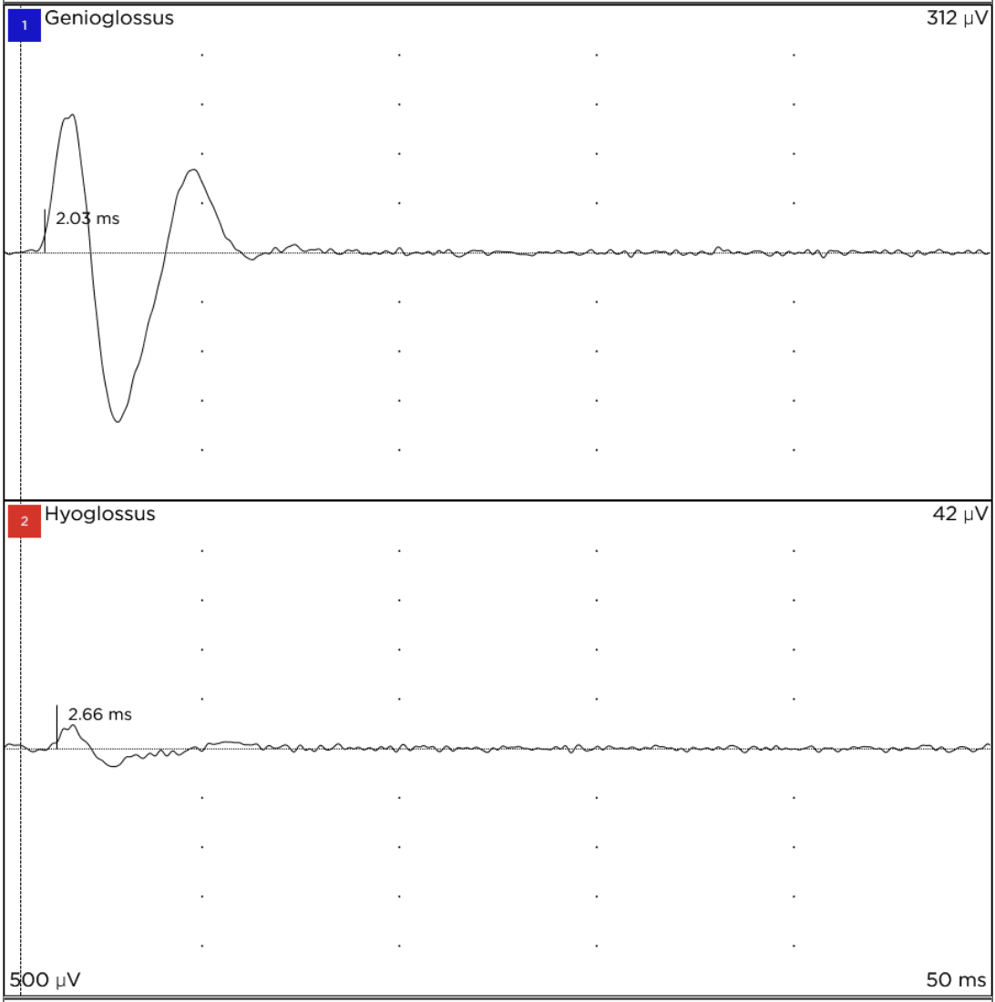
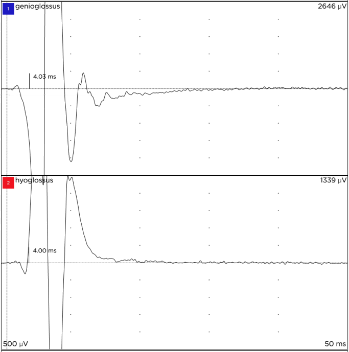
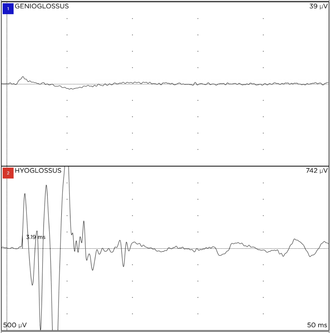
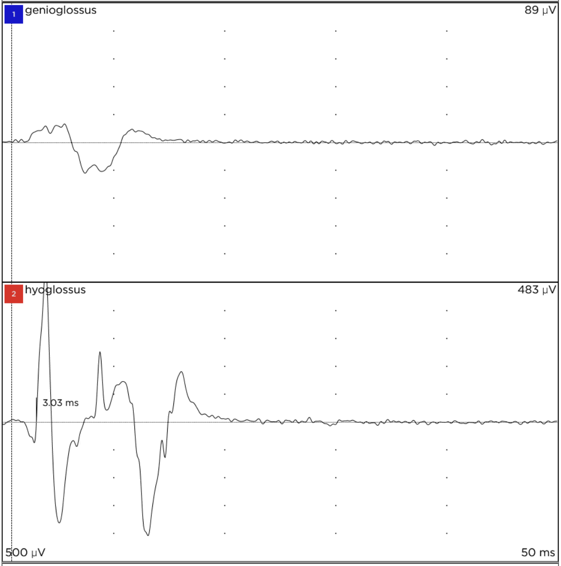
Recognize the four NIM patterns
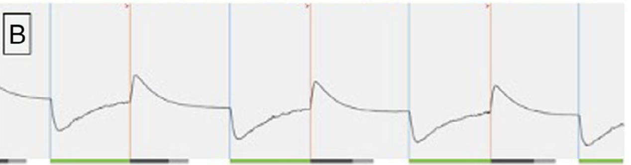
These quiz readouts use blue for channel 1 (upper) and red for channel 2 (lower). The original red-channel label is “Hyoglossus”; the prep lesson teaches styloglossus placement. Both are tongue retractors. Confirm your electrode and channel map before interpreting a tracing.
What to recognize: Both channels respond strongly over a similar interval. The lower, red-labeled channel returns to baseline without a distinct late tail.
What it means: This quiz example shows a transverse/vertical inclusion pattern. These intrinsic tongue muscles contribute to stiffening. Red-channel activity alone does not establish an exclusion response.
Apply it in the case: Confirm the expected tongue shape and movement, and relate the response to the stimulated branch. The displayed channel labels are the original recording labels; they do not change to T/V for this pattern.
What to recognize: The lower, red-labeled channel has a robust response with minimal activity in the upper channel. Notice the prolonged, low-amplitude tail after the larger red-channel response.
What it means: The quiz identifies this as hyoglossus recruitment, an exclusion response. Hyoglossus contributes to tongue retraction.
Apply it in the case: Confirm the retractor response, identify the exclusion branch, and preserve it outside the planned cuff contents.
What to recognize: There is a response in the upper, blue-labeled channel, but the lower, red-labeled response continues beyond it. The sharp, jagged red-channel peaks are another clue in this example.
What it means: Inclusion and retractor recruitment coexist. Seeing an inclusion response does not rule out an unwanted retractor response.
Apply it in the case: Recheck the stimulation site and tongue movement. Look for a retained retractor branch, complete its separation from the inclusion group, and repeat mapping before choosing the cuff segment.
Compare the timing and shape of the responses as well as amplitude. A late red-channel response is a useful clue in the mixed example, but no single waveform feature identifies every case. Reconcile each tracing with the stimulated branch and visible tongue movement.
Inspect beneath the nerve 0:59 · Shared technique · Silent · Written viewing guide
Watch for: Follow the inspection beneath the nerve and repeat stimulation. Compare the response with the exposed branches and look for a retained retractor when the findings do not agree.
Written video guide
0:00–0:15: Inspect the exposed branches before accepting the initial map.
0:18–0:35: Follow the inspection beneath the nerve and repeat stimulation.
0:39–0:57: Look for a retained retractor branch before accepting the dissection.
Source: Ryan Nord, MD. Shared neck technique; recorded implant model not identified
Work through the steps
Confirm the channel map. Confirm each recording electrode’s position and channel label before interpreting the tracing.
Know exactly what was stimulated. Place the probe on a defined structure and explain its position relative to the breakpoint. Current spread or direct muscle stimulation can complicate interpretation.
Compare patterns across test points. Use reproducible stimuli and compare amplitude, timing, and waveform shape with the examples above. T/V inclusion can produce activity in both channels. Red-channel activity or irregularity alone does not establish mixed recruitment.
Look at the tongue each time. Describe direction, shape, and stiffness rather than only signal height. A visually mixed or retracting tongue response demands reassessment even with a reassuring trace.
Resolve a discordant response. Recheck electrode seating and the stimulation site. Inspect the distal branch dissection, including beneath the nerve, for a missed retractor branch. Repeat mapping after improving exposure.
Separate the two displays. Tongue EMG records muscle recruitment during stimulation. The Inspire programmer’s respiratory waveform assesses sensing. A normal respiratory waveform does not confirm that the cuff captures only the intended branches.
Dr. Nord’s teaching
“So that's a good example of where the NIM looks good, but there's probably still a retractor.”
Know which muscle each channel records. Interpret the tracing together with the branch being stimulated and the visible tongue response.
Transverse/vertical (T/V) recruitment can produce activity in both channels. Compare timing, waveform shape, and amplitude; red-channel activity alone does not establish exclusion.
If the tongue retracts or the response does not fit the anatomy, recheck electrode placement, the stimulation site, and the branch dissection.
Pitfalls
Interpreting channel colors without confirming which muscle each electrode records.
Calling red-channel activity exclusion or mixed activation without comparing it with the T/V pattern.
Accepting a tall, smooth tracing despite visible tongue retraction or a retained retractor branch.
Confusing tongue EMG with the Inspire programmer’s respiratory sensing waveform.
Practice with real signals. In study mode, name the pattern before revealing the answer. Then explain how anatomy and tongue motion would confirm your interpretation.
Before moving on: Explain whether the NIM tracing and tongue movement agree with the branch anatomy. If they do not, describe what you would check next.
Place the cuff around the fully mapped inclusion group, confirm flap seating, and protect the nerve from tension with a relaxed lead loop and secure anchor.
Cuff handling and seating 0:58 · Shared technique · Silent · Written viewing guide
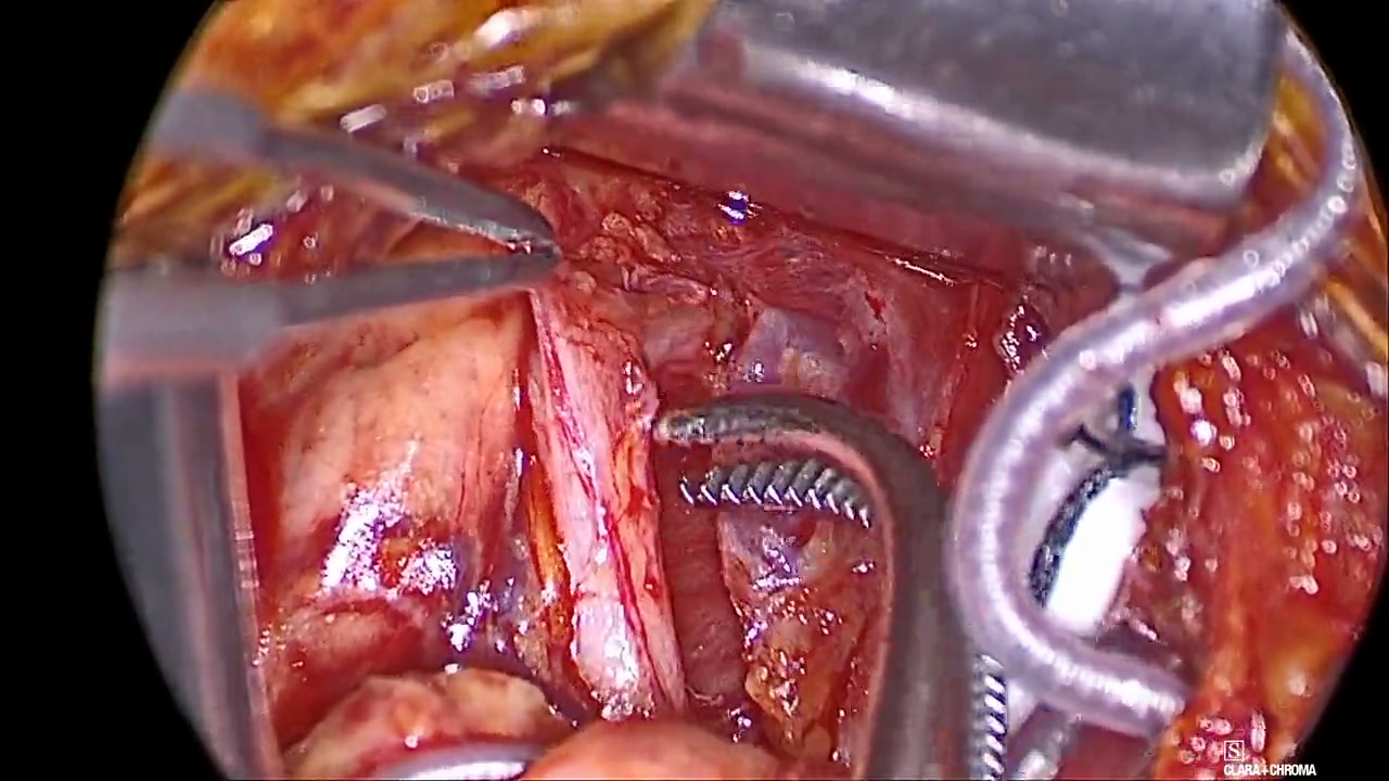
Watch for: Watch the direction of the right-angle tips and where the cuff is grasped. Follow its passage beneath the nerve, then inspect the inner and outer flaps.
Written video guide
0:00–0:15: Watch the point of grasp and its relationship to the nerve.
0:20–0:39: Follow the cuff around the selected inclusion branches.
0:42–0:57: Inspect cuff orientation and flap seating before system testing.
Source: Ryan Nord, MD. Shared neck technique; recorded implant model not identified
Work through the steps
Confirm the inclusion group. Confirm the completed branch dissection with the attending. Check that there is enough space to pass the cuff without force or traction on the nerve.
Pass the cuff. Turn the right-angle tips toward open space before grasping the posterior aspect of the cuff. This allows the cuff to pass beneath the nerve without folding in on itself. Keep the nerve, flap, and instrument tip in view as the cuff settles around the inclusion group.
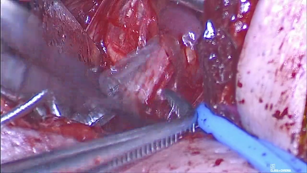
Inspect the full wrap. Confirm that the intended branches are enclosed and that the inner and outer flaps are correctly seated, without trapped fascia or a folded edge. The outer flap has chamfered edges; the inner flap does not. The short inner flap covers the nerve, and the longer outer flap closes over the inner flap. Reversing the flaps can prevent effective stimulation and tongue protrusion at testing. The cuff should settle around the nerve without being tightened.
Irrigate and recheck contact. Note the amount of space between the nerve and the cuff; a smaller nerve leaves a larger gap. Irrigate the nerve–cuff interface with saline to displace air, then inspect seating and contact again before interpreting a weak or absent response.
Smaller nerves may require a higher stimulation voltage intraoperatively, and a response near the lower threshold may pulse on and off. Check seating, flap orientation, and saline contact before attributing an intermittent response to nerve size.
As tissue fills the space during healing, contact can improve. A small nerve can still achieve effective stimulation after healing; the intraoperative threshold does not necessarily predict the later threshold.
Create strain relief and anchor. Place the relaxed lead loop beneath the submandibular gland and secure the designated lead anchor to the digastric tendon. Recheck that the loop provides slack and that the cuff remains seated when the wound and retraction relax.
Protect the hardware. Handle the lead body with sterile-gloved hands, as specified in the implant manual. Instruments may be used on the designated anchor. Avoid pinching, sharp bends, and traction. Keep suture bites away from the lead body; sutures secure the anchor, and the cuff is not sutured around the nerve.
Padded-forceps variation: suture booties over the tips of DeBakey forceps help prevent crimping during lead handling. The implant manual does not specify an exception for padded forceps.
Dr. Nord’s teaching
“Come underneath, and then you have to turn your tip so that you have a space where you can actually come in and have some space to place this cuff.”
Turn the right-angle tips toward open space, then grasp the posterior aspect of the cuff to pass it beneath the nerve without folding.
Seat the short inner flap over the nerve and the long outer flap over the inner flap. The outer flap has chamfered edges; the inner flap does not.
Note the gap between the nerve and cuff, then irrigate with saline to displace air. A smaller nerve may need a higher intraoperative stimulation voltage; recheck seating and contact before attributing a weak response to nerve size.
Place the relaxed lead loop beneath the submandibular gland and secure the lead anchor to the digastric tendon.
Pitfalls
Forcing the cuff through an inadequate opening or allowing it to fold during passage.
Reversing the inner and outer flaps or trapping fascia between the nerve and cuff.
Anchoring the lead without leaving a relaxed loop beneath the submandibular gland.
Suturing around the cuff or catching, crimping, or kinking the lead body.
Before moving on: Confirm that the intended branches are enclosed, the flaps are correctly seated, and the relaxed lead loop and digastric-tendon anchor prevent tension on the cuff.
Watch for: Follow the superficial course of the tunneler and watch the tip emerge through the prepared opening. Passage should require very little resistance.
Written video guide
Shape the tunneler to follow a superficial course beneath the skin, typically with a J-shaped bend, so the tip emerges through the prepared opening.
Watch the superficial passage and the tip emerging through the prepared opening.
The source slide teaches a broad entrance—a “funnel, not a tunnel”—and passage with very little resistance.
Source: Ryan Nord, MD. Shared principle; recorded implant model not identified
Inspire V generator placement 0:28 · Inspire V · Silent · Written viewing guide
Watch for: For a system with a separate respiratory sensing lead, watch the intercostal dissection. The source slide cautions against forcing the sensor into internal intercostal fibers and recommends correcting an inadequate signal.
Written video guide
0:00–0:18: This separate sensing-lead step applies to earlier systems. Inspire V senses respiration through the generator.
0:22–0:40: Follow the intercostal dissection and identify the intended tissue plane.
0:43–1:00: Watch the sensor’s relationship to the internal intercostal muscle fibers. Avoid forcing it into the muscle.
Source: Ryan Nord, MD. Legacy system with a separate respiratory sensing lead; not an Inspire V step
Work through the steps
Create the planned pocket. Develop the chest pocket superficial to the pectoralis fascia, typically about three fingerbreadths wide, with room for the generator and a relaxed lead arrangement. Keep the fascia intact over the pectoralis muscle. Disrupting this layer can cause bleeding and a delayed hematoma. Maintain hemostasis as you develop the pocket.
Open the route from each incision. At the neck incision, place two double-pronged skin hooks on the inferior skin flap and elevate it to visualize the platysma. Use a tonsil clamp with the tips directed up toward the flap to develop a broad subplatysmal dissection.
Keep the platysma clearly visible on the undersurface of the elevated flap as you advance. If you see fat on that surface, you are too deep, in the plane containing blood vessels. Return to the plane immediately beneath the platysma.
Prepare a broad entrance from each incision so the tunneler can pass without forcing a narrow track.
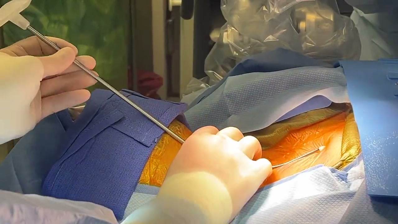
Keep the tunneler superficial. Alert anesthesia before passing the tunneler. Tunneling is a strong surgical stimulus, and anesthesia can be deepened as needed. Follow the subplatysmal and subcutaneous route superficial to the clavicle. If resistance increases or the course becomes unclear, stop and recheck the path before advancing.
Pass the stimulation lead. Pass the stimulation lead through the prepared tunnel while preserving slack at the neck and chest. Avoid transmitting traction to the cuff. Check that the lead follows a smooth course without sharp bends or kinks.
Connect and verify retention. Keep the stimulation-lead connector and the implantable pulse generator (IPG) port dry. Fully insert the connector pin into the IPG until its tip is visible past the set screw block. Tighten the set screw with the supplied torque wrench, then recheck the pin position and gently check retention at the strain-relief segment.
Incomplete insertion can cause poor or absent stimulation. If you see a shark-fin waveform during testing, recheck the lead connection and confirm that the stimulation pin is fully seated.
Shark-fin respiratory waveform
Recognize the abrupt deflections and sloping return of this shark-fin waveform. An abnormal tracing during testing should prompt reassessment of the system, including the lead connection.
Source: Islam et al., Respiratory Sensing Lead Malfunction in Upper Airway Stimulation (2024), Figure 3B. View full-size image
Seat and secure the generator. Arrange excess lead without tension, seat the generator in its specified orientation, and secure fixation. Confirm the lead is protected before the final test.
Dr. Nord’s teaching
“if you're on the right plane it just goes like butter basically”
Keep the pectoralis fascia intact when creating the generator pocket. The pocket is typically about three fingerbreadths wide.
Elevate the inferior neck flap with two double-pronged skin hooks and keep the platysma visible as you open a broad subplatysmal plane. Fat on the undersurface of the flap means the dissection is too deep.
Alert anesthesia before tunneling. Keep the tunneler superficial and expect very little resistance.
Preserve lead slack while connecting and seating the generator so traction is not transmitted to the cuff.
Confirm that the stimulation pin extends past the set screw block. Recheck insertion and retention after tightening the screw.
Pitfalls
Disrupting the pectoralis fascia during pocket creation, which can cause bleeding and a delayed hematoma.
Dissecting too deeply beneath the platysma and entering the vascular plane.
Tunneling beneath the clavicle or forcing the tunneler against resistance.
Pulling on the lead body or removing lead slack while connecting and seating the generator.
Failing to confirm that the stimulation pin is visible past the set screw block, or skipping the lead retention check.
Before moving on: Confirm full connector insertion and lead retention. Check that the generator is secure and the lead follows a relaxed, protected course.
Published references for this lesson
Inspire V system implant manual (3150 / 4063). 200-541-101_EN, revision C, September 22, 2025. Printed pages 23–25 and Figure 11: dry connector and port, pin visible past the set screw block, torque-wrench fixation, and retention check at the strain relief. Verified September 6, 2026.
Check respiratory sensing and the tongue response across electrode configurations. Work through any unexpected findings, then close and dress the wounds.
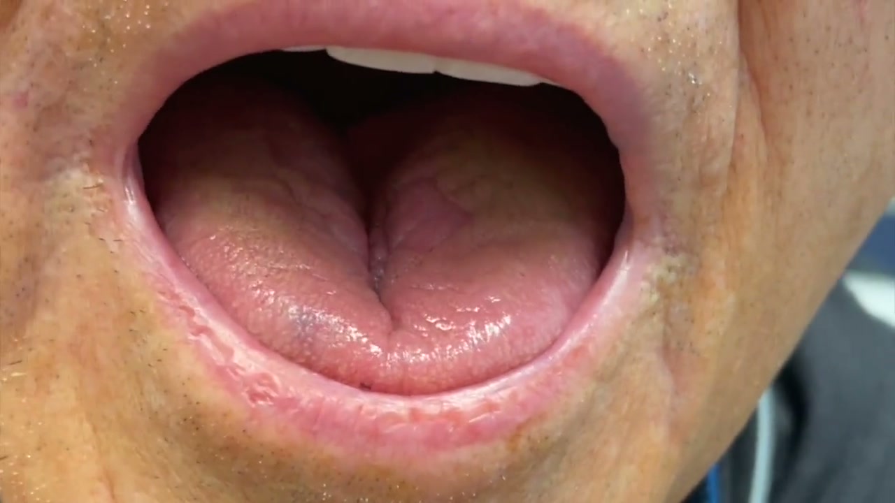
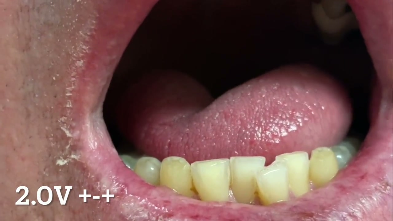
Watch for: Compare the direction of movement with the protrusion example. The displayed voltage and configuration belong to this recorded case; use the testing sequence below for the lesson’s stepwise assessment.
Written video guide
0:00–0:06.75: Observe the direction of movement. The displayed setting belongs to this recorded example.
Source: Ryan Nord, MD. Shared principle; recorded implant model not identified
Retraction prompts another look 3:00 · Shared technique · Silent · Written viewing guide
Watch for: Follow the return from an unexpected tongue response to inspection of the nerve and cuff, then compare the response after repeat testing. The displayed settings belong to this recorded case.
Written video guide
0:00–0:24: Follow cuff and nerve assessment, tongue movement, and repeat testing.
0:30–1:11: Assess the initial tongue response. The displayed voltages are from this recorded case.
1:20–2:09: Watch the return to the nerve and cuff for further assessment.
2:20–2:59: Compare the later tongue response with the initial response.
Source: Ryan Nord, MD. Shared principle; recorded implant model not identified
Work through the steps
Check the waveform. For Inspire V, run the respiratory waveform at 0 V, without stimulation, and confirm that the signal follows respiration. The generator contains a three-axis accelerometer. The waveform may change over time as the sensing algorithm evaluates the axes and selects the best respiratory signal. Allow time for sensing to stabilize before interpreting the tracing.
Test configuration A, then B. Electrode configuration affects nerve recruitment and the resulting pattern of tongue protrusion. Always test at least configurations A and B. With the team able to see the tongue, assess protrusion, stiffening, and any retraction at each setting. Record the configuration, voltage, and tongue response.
Configuration A (+ − +): start at 1.5 V, then decrease to 1.2, 1.0, 0.7, 0.5, and 0.3 V. Strong protrusion at a higher voltage can give way to retraction or mixed activation at a lower voltage.
Configuration B (o − o): start at 0.5 V, then decrease the voltage stepwise while watching for mixed activation. Confirm the response in both configurations.
Configuration C (− o −) uses the two outer cuff contacts as cathodes, with the middle contact inactive. Current may reach a nearby retractor branch outside the cuff and produce mixed activation. A mixed response in C alone does not establish that a retractor is captured inside the cuff. Compare the responses in A and B with the branch anatomy.
If doubt about a retractor within the cuff remains after this assessment, remove the cuff and inspect again for a small retractor branch. Complete the dissection and repeat branch mapping, then replace the cuff and repeat testing.
For absent stimulation, irrigate the cuff first. Irrigate saline into the cuff to displace air at the nerve–cuff interface, then repeat stimulation. If there is still no response, inspect cuff seating, flap orientation, and contact.
Then check the generator. Confirm that the stimulation pin is visible past the set screw block and that the lead is retained. Review communication and the actual programmed test settings. Confirm the monitoring and anesthetic conditions if the response remains unclear.
Then check the nerve again. Revisit branch identity and the completed dissection. If testing in A or B raises concern for a retractor within the cuff, or the branch anatomy remains uncertain, remove the cuff and inspect distally and underneath for a small late retractor. Repeat branch mapping, replace the cuff, and test both configurations again.
Complete the system check. Complete the generator check and reconfirm respiratory sensing. Document the lowest voltage that produces the intended tongue response in each tested configuration, and confirm therapy is off before completion. Resolve any discrepancy while the operative field remains accessible.
Closure and wound dressing
Inspect before closing. Reconfirm hemostasis, cuff seating, lead slack, anchor fixation, and generator position. Irrigate with saline containing vancomycin, then check that no tissue or retraction change has placed the lead under tension.
Close without catching the lead. Close in layers, keeping needles and suture bites clear of the lead.
Apply the wound dressing. Apply Mastisol, then arrange the Steri-Strips parallel to the wound. Cover with Telfa, folded gauze, and Tegaderm, in that order.
Dr. Nord’s teaching
“You might want to test on different electrode configurations and see if there's any difference”
For Inspire V, check the respiratory waveform at 0 V, without stimulation. The waveform may change as the sensing algorithm selects among the accelerometer’s three axes; allow sensing to stabilize and assess how the signal follows respiration over time.
Always test configuration A (+ − +) from 1.5 V down to 0.3 V, then B (o − o) from 0.5 V downward. Configurations can produce different tongue-movement patterns. Watch at every setting; strong protrusion at high voltage can conceal mixed activation at lower voltage.
Configuration C (− o −) may recruit a nearby retractor outside the cuff. Mixed activation in C alone does not prove that a retractor is enclosed. Compare A and B with the anatomy; if doubt remains, remove the cuff, inspect the branches, remap, and retest.
For absent stimulation, first irrigate saline into the cuff and retest. If there is still no response, check cuff seating, flap orientation, and contact; then check the generator and connections, followed by the nerve.
Pitfalls
Accepting strong protrusion at 1.5 V without checking for retraction or mixed activation as the voltage decreases.
Testing only configuration A and skipping the lower-voltage assessment in configuration B.
Leaving the cuff in place when the A/B responses or branch anatomy still raise concern for a retained retractor.
Treating mixed activation in C alone as proof that a retractor branch is inside the cuff.
Increasing stimulation amplitude for an absent response before irrigating saline into the cuff and retesting.
Treating a normal respiratory sensing waveform as proof that the cuff captures only the intended branches.
Before moving on: Confirm the respiratory waveform and tongue response in A and B, with any mixed activation addressed. Check lead slack before closure and review the dressing sequence.
Inspire SleepSync Programmer Manual. 200-483-001, revision G, January 2, 2026. Pages 60 and 86: Model 3150 waveform display at 0 V, sensing stabilization, and the generator check. Waveform assessment is optional during implantation; the generator check is the primary motion-sensor check.
Sturm et al. Intraoperative identification of mixed activation. Sturm JJ, Lee CH, Modik O, Suurna MV. J Clin Sleep Med. 2020;16:1769–1774. doi:10.5664/jcsm.8694. Low-intensity unipolar testing revealed mixed activation missed by standard bipolar testing. The discussion considers current spread outside the cuff but regards it as unlikely at the low intensities studied. Configuration C was not tested.
Short clips from Dr. Nord’s operative teaching videos. Each opens within its lesson, with a viewing prompt and a written guide.
Real operative footage. The lessons distinguish earlier sensing-lead chest work from Inspire V.
16 clips
Incision planning and orientation
0:32
Practice palpating the submandibular gland (SMG) with one finger. Use light pressure and feel the anterior edge roll beneath your finger. With experience and continued practice, this landmark becomes easier to identify, even in patients with obesity. The anterior gland edge is the key anchor for accurate incision placement. Locate it first, then use the incision measurements in this lesson to place the mark.
Start with the earlier neck exposure and identify the submandibular gland (SMG). Keep the gland as your landmark as the dissection proceeds toward the digastric and mylohyoid. Then watch the next clip for a closer view of the mylohyoid free edge.
This teaching case shows the nerve to mylohyoid producing an apparent inclusion response on NIM, followed by correct identification of the hypoglossal nerve. Recognize the mylohyoid free edge and the hyoglossus to orient the dissection and identify the correct nerve.
The lingual nerve lies superior to the hypoglossal nerve, but at times can lie lower than expected and cause confusion. Use its anatomic course to distinguish it from the hypoglossal nerve.
Watch how the crossing vein is isolated, sealed, and divided to improve the view of the nerve and its branches. Follow the instrument tips and their relationship to the nerve throughout the maneuver.
Use the longitudinal vessel to estimate the initial breakpoint. Preserve it during branch separation, then inspect distally for a late retractor. A reassuring NIM response does not establish that the dissection is complete.
Identify the anterior free edge of the hyoglossus and use it to judge how far distally the nerve has been exposed. Inspect near and just beyond this edge for a small late retractor branch before accepting the final breakpoint.
Follow the inspection beneath the nerve and repeat stimulation. Compare the response with the exposed branches and look for a retained retractor when the findings do not agree.
Watch the direction of the right-angle tips and where the cuff is grasped. Follow its passage beneath the nerve, then inspect the inner and outer flaps.
For a system with a separate respiratory sensing lead, watch the intercostal dissection. The source slide cautions against forcing the sensor into internal intercostal fibers and recommends correcting an inadequate signal.
Compare the direction of movement with the protrusion example. The displayed voltage and configuration belong to this recorded case; use the testing sequence below for the lesson’s stepwise assessment.
Follow the return from an unexpected tongue response to inspection of the nerve and cuff, then compare the response after repeat testing. The displayed settings belong to this recorded case.
These checks support preparation and discussion. Completion and quiz scores do not establish operative competence or replace supervised surgical training and the current device instructions.
The pathway draws on Dr. Nord’s operative teaching: surgical pearls, intraoperative troubleshooting, and nerve dissection technique. Published references are listed beside each lesson and below. The lesson priorities also reflect recurring coaching themes from resident operative feedback, including exposure before nerve work and confirmation of the full branch pattern.
The recommendations present a teaching approach for supervised implant surgery. Use the applicable implant manual for device-specific handling. Confirm the device generation, current labeling, and your supervising surgeon’s plan before the case.
A branch selected for the cuff because its activation contributes to the intended tongue response.
Exclusion branch
A branch kept outside the cuff because its activation opposes the intended response, particularly through retraction.
Breakpoint
The operative functional division between intended inclusion and exclusion branches; the anatomy varies.
Mixed activation
Recruitment of muscles with opposing effects, such as protrusion together with retraction.
CN XII
The hypoglossal nerve.
SMG
The submandibular gland.
Marginal mandibular branch (MMN)
The facial nerve branch to the lower-lip depressors, the mentalis, and the facial part of the platysma. It crosses the mandibular border superficial to the facial vessels and runs along the mandible, above the Inspire neck incision.
Cervical branch (CBFN)
The facial nerve branch to the platysma. Its first branch runs within the investing fascia over and in front of the submandibular gland, just outside the capsule, and ends at the mandible where the lower-lip depressors attach. It is the facial nerve branch at risk in the Inspire neck exposure.
Depressor labii inferioris (DLI)
The muscle that pulls the lower lip down. It works as one unit with the platysma and is supplied by both the marginal mandibular and the first cervical branch.
Genioglossus
The major tongue protrusor targeted during selective stimulation.
Hyoglossus
An extrinsic tongue muscle that contributes to retraction. Its anterior edge is a landmark for distal branch dissection.
T/V
Transverse and vertical intrinsic tongue muscle fibers that contribute to tongue shape and stiffening.
C1 / geniohyoid
First cervical nerve fibers traveling with CN XII to geniohyoid; identify them and discuss the intended cuff map.
NIM / tongue EMG
Nerve integrity monitoring records tongue muscle responses to stimulation using electromyography (EMG). This module uses the NIM Vital system. Tongue EMG is distinct from the Inspire generator’s respiratory sensing waveform.
IPG
Implantable pulse generator.
Strain relief
A relaxed lead arrangement that limits tension transmitted to the nerve and hardware during movement.
VOTE
DISE description by velum, oropharynx, tongue base, and epiglottis, with degree and configuration of collapse.
Wishbone Sign
Nerve bundles that come back together distal to the spreading instrument at the initial inclusion–exclusion breakpoint indicate a small retained retractor branch that needs further dissection.
Vasa nervorum
Small vessels that supply a nerve. The longitudinal vessel shown in this module helps identify the plane between inclusion and exclusion fibers and is preserved during dissection.
Crossing ranine-vein branch
A small venous branch crossing over the hypoglossal nerve. It is isolated and divided to expose the underlying branches; in the operative example, it also marks the distal region near the final breakpoint.
Electrode configuration
The pattern of active and inactive stimulation contacts. This module tests configuration A (+ − +), then configuration B (o − o), where o denotes an inactive cuff contact.
Educational material for residents and clinicians. Includes real operative footage. Learning progress is kept only on this device if you choose to remember it. The NIM trainer opens separately. Site privacy notice.
Disclosures
Ryan Nord, MD, consulted for Inspire Medical Systems until 2025 and consults for AvivoMed. He has also consulted for Medtronic, which makes the NIM nerve monitor named in these lessons; that relationship has ended. He has received research support from Nyxoah, the maker of Genio, and has been a paid member of the clinical events committee for Nyxoah-sponsored trials. This is his personal educational website. The education center adapts his teaching materials for resident education; it is not a manufacturer training credential. See the full disclosures for his industry relationships and how to report a content correction.